|
MPU Extension
by Ralph Moore
November 30, 2021
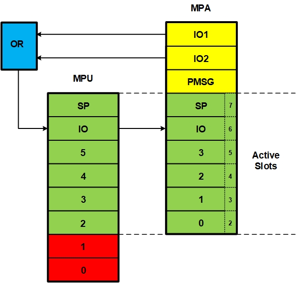
In any real project using a secure RTOS with a Memory Protection Unit (MPU), you are likely to run out of MPU slots for at least some tasks. One group of culprits is peripheral drivers, which tend to require multiple IO regions. If you have only one region to give to your task, you may regret it. Said region is likely to span many IO addresses that the task should not access, lest it be hacked. The figure below shows a solution to this problem from my tech paper, Achieving Full MCU Partition Isolation, MPU Management:
I decided to apply this solution to the LED task in the SMX Protosystem. For this task, the MPA[1] template was:
MPA mpa_tmplt_led =
{
   RGN(0 | RA("ucom_code")  | V, CODE   | SRD("ucom_code") | RSIC(ucomcsz) | EN, "ucom_code"),
   RGN(1 | RA("ucom_data")  | V, DATARW | SRD("ucom_data") | RSIC(ucomdsz) | EN, "ucom_data"),
   RGN(2 | RA("led_code")   | V, CODE   | SRD("led_code")  | RSIC(ledcsz)  | EN, "led_code"),
   RGN(3 | RA("led_data")   | V, DATARW | SRD("led_data")  | RSIC(leddsz)  | EN, "led_data"),
   RGN(4 | 0x40020000       | V, IOR    | N0|N2|N3|N4|N67  | (12 << 1)    | EN, "GPIOBF"),
   RGN(5 | 0x40005400       | V, IOR                       | ( 9 << 1)    | EN, "I2C1"),
   RGN(6 | 0x40023800       | V, IOR                       | ( 9 << 1)    | EN, "RCC"),
   RGN(7 | V, 0, "stack"),
  }
This task needs regions GPIOB and GPIOF, but region 4 spans 3 more GPIO regions (C, D, and E). After applying the change shown in the above figure the MPA template is now:
MPA mpa_tmplt_led =
{
   RGN(0 | RA("ucom_code")  | V, CODE   | SRD("ucom_code") | RSIC(ucomcsz) | EN, "ucom_code"),
   RGN(1 | RA("ucom_data")  | V, DATARW | SRD("ucom_data") | RSIC(ucomdsz) | EN, "ucom_data"),
   RGN(2 | RA("led_code")   | V, CODE   | SRD("led_code")  | RSIC(ledcsz)  | EN, "led_code"),
   RGN(3 | RA("led_data")   | V, DATARW | SRD("led_data")  | RSIC(leddsz)  | EN, "led_data"),
   RGN(4 | V, 0, "GPIO"),
   RGN(5 | 0x40005400       | V, IOR    | (9 << 1) | EN, "I2C1"),
   RGN(6 | 0x40023800       | V, IOR    | (9 << 1) | EN, "RCC"),   /* for timeout error */
   RGN(7 | V, 0, "stack"),
   RGN(8 | 0x40020400       | V, IOR    | (9 << 1) | EN, "GPIOB"), /* aux region */
   RGN(9 | 0x40021400       | V, IOR    | (9 << 1) | EN, "GPIOF"), /* aux region */
};
Notice that auxiliary regions 8 and 9[2] have been added and that region 4 is now an open region.
Then I ran into a surprise — the sb_LEDWriteRow() subroutine, which is called from the LED task requires both GPIO regions. It is supposed to be callable from other tasks, thus it cannot do region switching for the LED task. So it was necessary to split sb_LEDWriteRow() into two subroutines: sb_LEDWriteRowB() and sb_LEDWriteRowF(), which are called by a new version of sb_LEDWriteRow() for the LED task (LT) that does a region swap ahead of each subroutine. In the LED task code, the following were added:
#define sb_LEDWriteRow sb_LEDWriteRowLT
and:
void sb_LEDWriteRowLT(u32 val)
{
   mp_MPASlotMove(4, 9);   /* MPU[4] = GPIOF */
   sb_LEDWriteRowF(val);
   mp_MPASlotMove(4, 8);   /* MPU[4] = GPIOB */
   sb_LEDWriteRowB(val);
}
If another task required the same GPIO regions to be switched, it would require its own version of the above code using appropriate region numbers for it. So, using auxiliary slots for GPIO regions works, but it does require some modification of the application code. The mp_MPASlotMove(m, n) function runs in pmode and is accessed via an SVC exception. Its arguments, m and n, must be valid slots in the current task's MPA. Thus a hacker could mess up the current task and its partition, by calling this function, but not tasks in other partitions.
Although adding MPU slot switching requires some modification of the application code, the amount of code added or changed is likely to be minimal,. The time overhead per region switch is that of the mp_MPASlotMove(m, n) function (15 lines of C code) plus the SVC handler (40 assembly instructions). This is negligible for the LED task since the LEDs change only once a second. But it might not be negligible in other cases.
If the task code is complicated, one might be reluctant to attempt region switching. The basic idea is to switch to a region ahead of the code that needs it. This is likely to be a subroutine or could be made into a subroutine. What if you don't? Then, when the application runs, an MMF will occur. The debugger call stack window will show exactly where the region switch is needed so you can add the region switch there. Note that all auxiliary regions being used by a task are stored in auxiliary MPA slots, so you do not need to save the current auxiliary region.
If region switching becomes overly complicated for a task or there are no regions that can be switched for it, other techniques can be applied. I will discuss these in future blogs.
Notes
[1] Each task has a Memory Protection Array (MPA), which is loaded into the MPU when the task starts running.
[2] The MPU has only 8 slots (0 to 7). Hence, these regions are called auxiliary regions, and they are not loaded into the MPU when a task switch occurs.
Ralph Moore is a graduate of Caltech. He and a partner started Micro Digital Inc. in 1975 as one of the first microprocessor design services. Now Ralph is primarily the Company RTOS innovator. He does all functions including product definition, architecture, design, coding, debugging, documenting, and assisting customers. Ralph's current focus is to improve the security of IoT and embedded devices through firmware partitioning. He believes that it is the most practical approach to achieving acceptable security for devices connected to networks and to the Cloud.
Copyright © 2021 Micro Digital, Inc. All rights reserved.
|